GSMGPRS based GPS Tracker using Blynk with Calling SMS fe Circuit Diagram The current design is an embedded application system. Arduino is a based tracking system using GPS and GSM modules. This system is used for tracking and positioning any location by using the Global Positioning System (GPS) and Global System for mobile communication (GSM). Tracking of Any Persons & Material is a process in which one can track Generally a GPS Module is used for any sort of location tracking but here in this tutorial we will use GSM SIM800 module to build a simple Location tracking system with Arduino. This GPRS tracking system compromises the GSM modem and the microcontroller (Arduino) and is fabricated on a PCB from PCBGOGO . Bill of Materials. The Arduino based GPS Tracker Project can be done in 2 ways. The first way is using a single integrated device that has a combined GSM + GPS + Microcontroller.The second way is using the different available GSM & GPS Modules available in the market along with the Arduino Board.
This project implements a Vehicle Tracking System using Arduino along with GPS and GSM modules. It allows tracking the vehicle's real-time location and sends this data to a web server for monitoring purposes. This system can be used for fleet management, theft prevention, or simply monitoring vehicle movement.

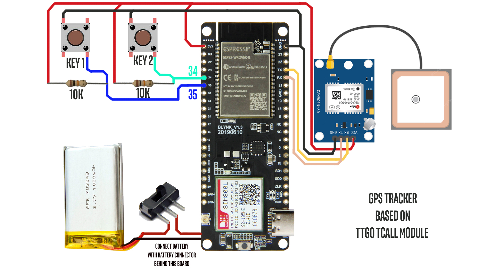
GPS+GSM Based Vehicle Tracking System using Arduino Circuit Diagram
The system should monitor the real-time requests from the user through the GSM module. So, by default the microcontroller maintains the connection with the GSM module i.e. the GSM module will be the UART terminal to the microcontroller and whenever the GPS data is required, the microcontroller selects the GPS module as the UART terminal through the logic circuit.
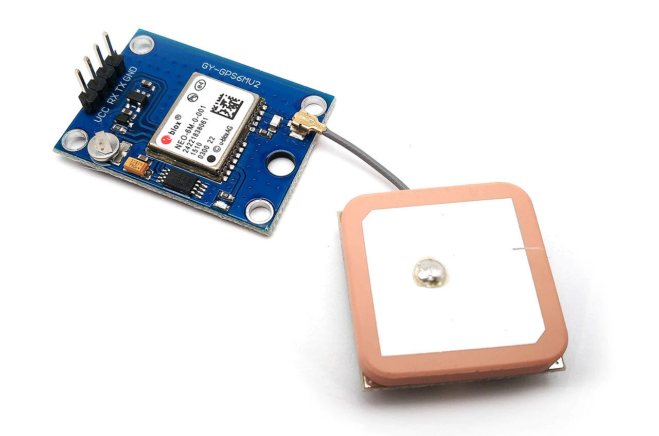
GSM Modem. This vehicle tracking system using GPS uses a SIM300 GSM modem. GSM modem transmits and receives the data. Modem SIM300 is a tri-band GSM/GPRS engine that works on frequencies EGSM 900 MHz, DCS 1800 MHz, and PCS 1900 MHz. Transmit pin TXD and receive pin RXD of the GSM modem are connected to the microcontroller (IC2) via MAX232 (IC3). GSM MODULE - SIM800L. Pretty tiny, easy-to-use ; Capable of using mobile internet (GPRS) Cheap; GPS MODULE - Ublox NEO6M. Also small ; Handles its job very well; A microcontroller - can be anything - you could use the famous Arduino Uno or the Nano to free up some space. Battery - I used a 18650 cell as the main, and only power source (Nominal Create a ThingSpeak channel Now, we must create a channel to communicate with the ThingSpeak server. Channels are where applications store and retrieve data on the ThingSpeak server. To create a channel, click the 'New Channel' button and fill in the form. Enter a name for your channel, such as 'GSM-GPS-Vehicle-Tracking.' Next, create

GPS Tracker with GSM/GPRS using blynk with SMS and ... Circuit Diagram
Here we make the real-time location information tracker, and also we sensor notifications to vehicle owners if anything happens. This is used in various fields but in this article, we only show the Vehicle Location Tracking System. Build Your Small GPS Tracking System; Vehicle Accident Alert System Using ADXL-335 Accelerometer Sensor GPS And GSM