Build an accurate bipolar voltage reference Circuit Diagram The downside to a voltage reference is that it only generates a single voltage and has limited current output. I decided to design a circuit that could generate any voltage between zero volts and 10 volts in 0.1 volt increments; for example, 4.8 volts with a basic accuracy of 10 millivolts and an output current of 100 milliamps (or one ampere

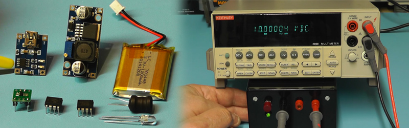
The real magic happens in the Texas Instruments REF102 precision voltage reference. You give it a decently clean 12-36 volts, and it will give you a 10 volt reference out.

Poor Man's Precision Voltage Reference Circuit Diagram
Phase 3: Build a professional proto The custom PCB version will be powered by battery as that will be desired. A boost converter for DAC voltage reference input and constant current circuit to work. I will also add isolated USB interface so that we can control the voltage current reference via PC. Display will be changed from OLED to a low power glass display which will consume 200-330uA while

How does one go about accurately setting reference voltages at various points in a given circuit (e.g. various threshold voltages). Obviously we can have a potential divider from the main power supply but that generally tends to fluctuate a lot, not to mention noise from other parts of the circuit. I would assume a sort of single voltage reference from which we can derive the rest of the
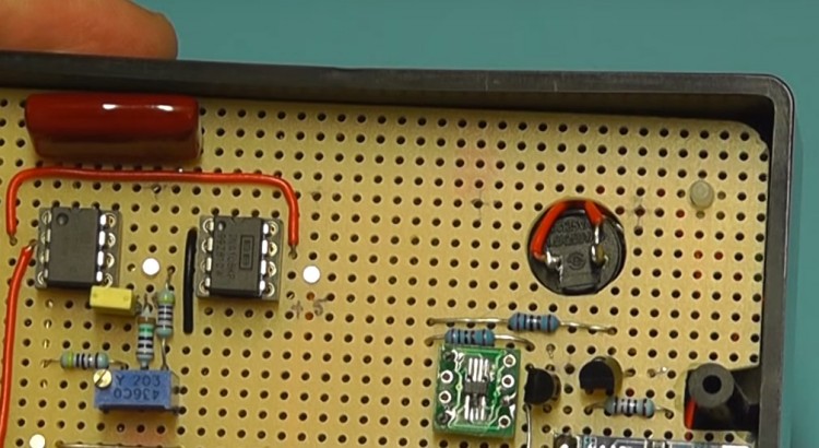
Build A Precision Voltage Reference Box Circuit Diagram
Other possible reasons include using one to calibrate your DMM, or to construct a precision voltage-to-frequency converter or current source. The applications for a precision reference fall into two general categories: instrument (DMM, DVM) calibration/accuracy verification, or as a circuit component, such as the reference for an A/D converter.